
Accomplishments
- 360 -> 3D End-to-End Proof of Concept
Recent weeks of research have outlined the problems that must be solved to deliver a pipeline where sparse 360 imagery can be accurately reconstructed into a 3D mesh. A variety of tools and algorithms were compared in order to support this process. Ultimately an initial pipeline was developed where with just two sparse 360 images a merged 3D mesh could be completed.
360 -> 3D End-to-End Proof of Concept Workflow
The whole process of converting 360 images into a 3D model requires a variety of smaller problems to be solved. The workflow intends to solve the following problems:
- Image downsampling
- Feature extraction
- Feature Matching
- Match Filtering
- Depthmap Estimation + Point Cloud Generation
- Convert matches to 3D
- Align point clouds
- Convert Point Cloud to Mesh
Image Downsampling
Image downsampling means to shrink an images size. This step is required to conform to a downstream tool’s image size requirement. Downsampling is a double edged sword. In this case, it greatly reduces processing time; However, it also reduces the detail used in identifying features and calculating depth. A future iteration may improve on this by downsampling later in the process.
Feature Extraction
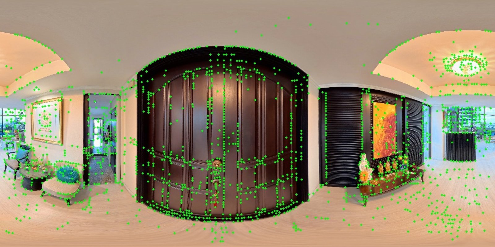
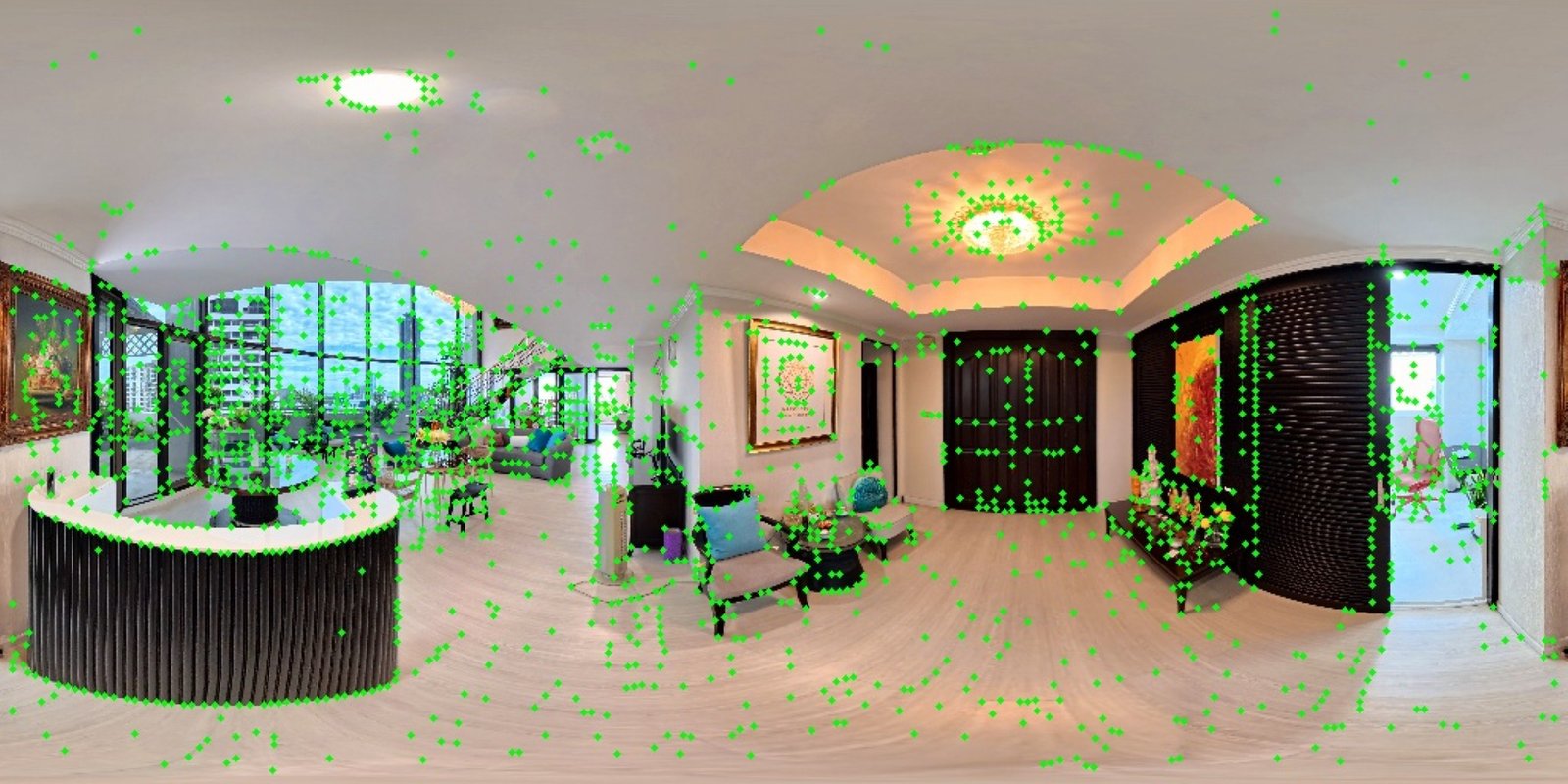
The feature extraction step looks for unique areas of pixels across an image. These coordinates are later used to compare two images and see what features may overlap.
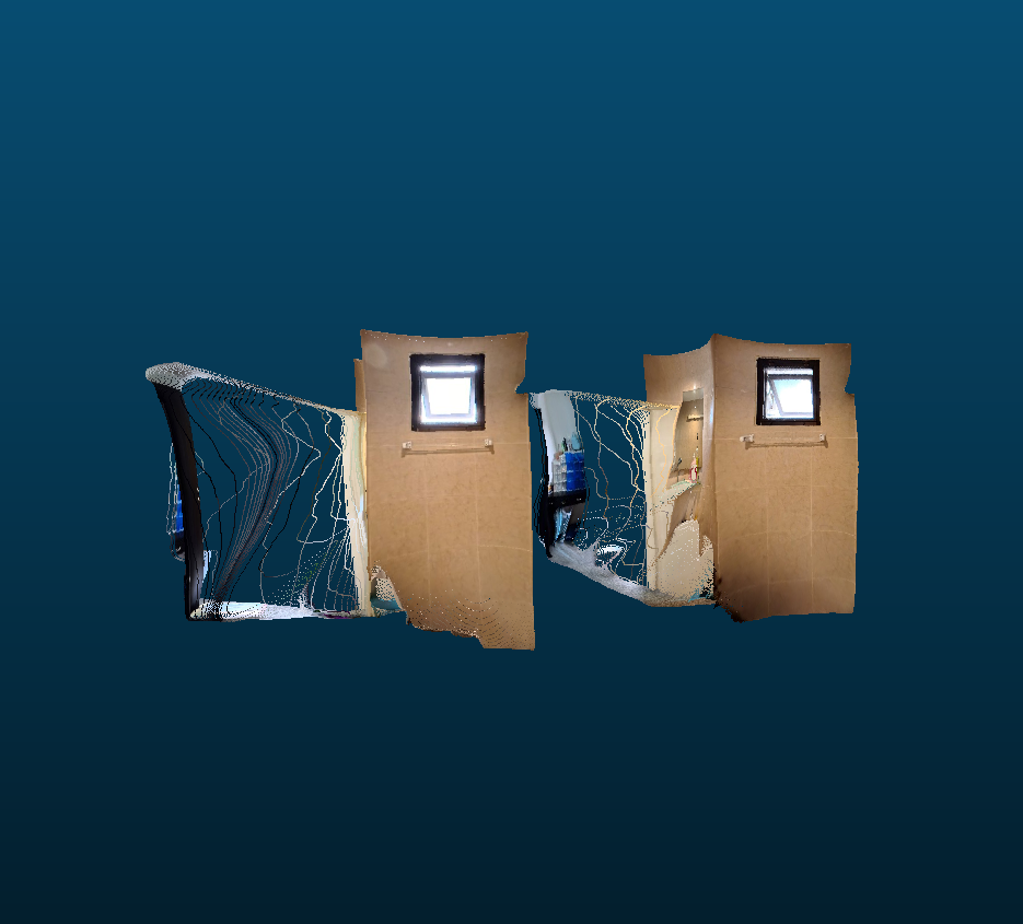
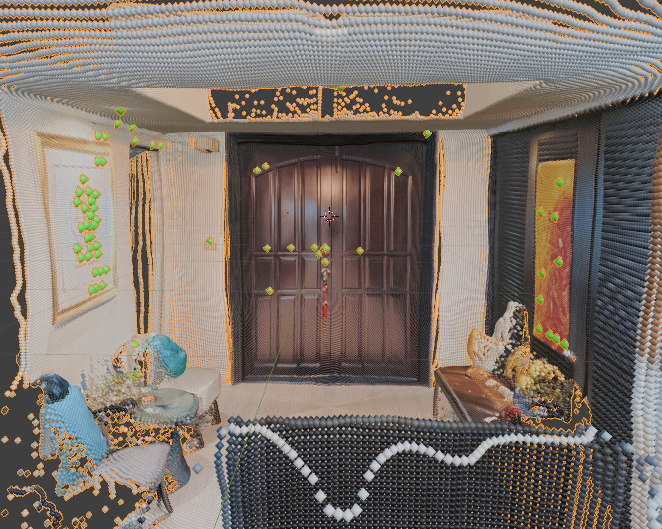
Feature Matching
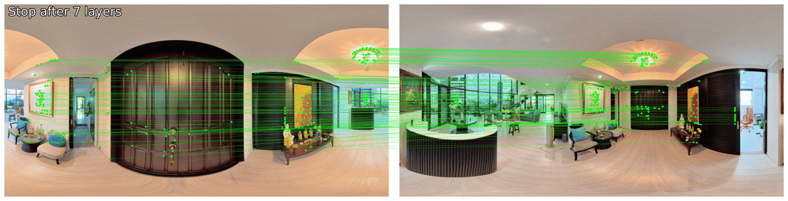
The features calculated in the previous step are compared across two images. The algorithm does it’s best to find groups of pixels that appear similar across the two images. In the example you might notice that some of the matches appear incorrect. The ceiling’s light fixture is very noticeable. The camera moves to the opposite side of the light. Because the fixture is symmetrical, the same features are found on both sides and incorrectly matched by the matcher. A smaller example can be seen on the black sliding doors.
Match Filtering
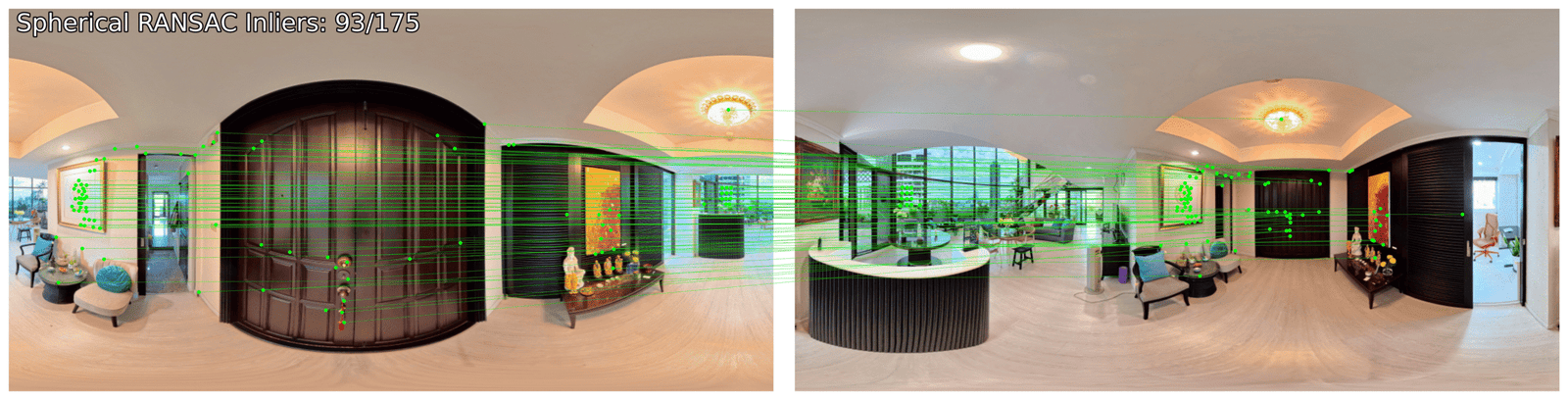
Special feature filtering techniques exist for equirectangular images which help to filter out false positives like those we found in the previous step. The result is far fewer matches, and a far higher percentage of valid matches. The density of matches on the main door and wall art largely remain, while the ceiling light and sliding door are almost entirely removed. Quality is preferred to quantity in this step, and will help us better align the output in a later stage.
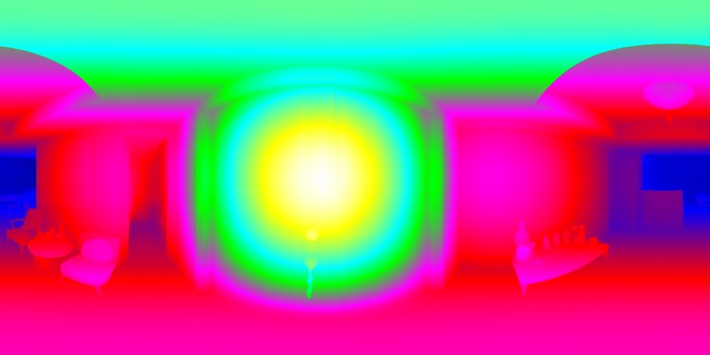
Depthmap Estimation + Point Cloud Generation
Comparing Techniques
In deciding which tool to use for depthmap and point cloud generation I began by comparing two tools. Tool A was built to accept equirectangular images and output point clouds with reliable metric depth. Tool B was built to accept equirectangular images and output point clouds with reliable relative depth.
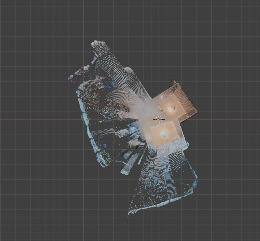
Testing Tool A
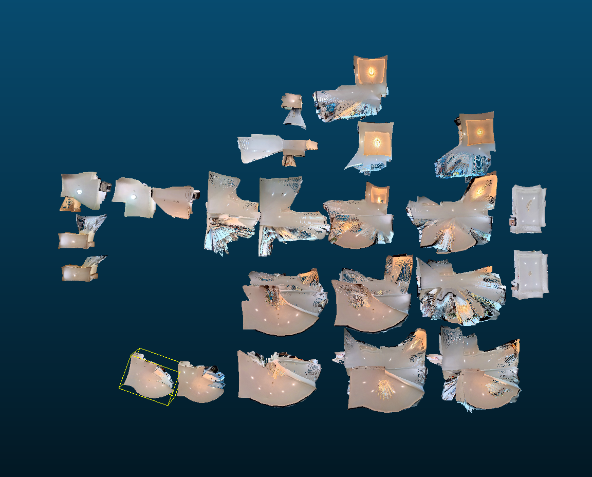
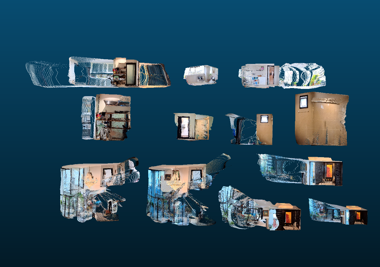
I ran a variety of equirectangular images through Tool A and laid out the output to visually assess the results. From the top and side view I notice surprising consistency in scale across the images. Each room appears to be the same size compared to other projections from the same room. Take note of the two examples of the storage closet washroom, as we will compare these with the output from Tool B.
There was an example where the scale of the room appeared to be almost half that of other similar images. Take a look at the living room comparison. The larger point clouds were consistent with the scale estimates across all the other point clouds. The smaller ones appear as a noticeable outlier. These photos were taken on the stairs at a different elevation from all the other photos. My best guess is that this is the result of a bias introduced in the AI model. Perhaps the AI model’s training data heavily favored images taken from the floor of a room compared to ones on a staircase. If this is true, the output may assume that the ceiling and floor are equally close and may pull them to the size of the average room.
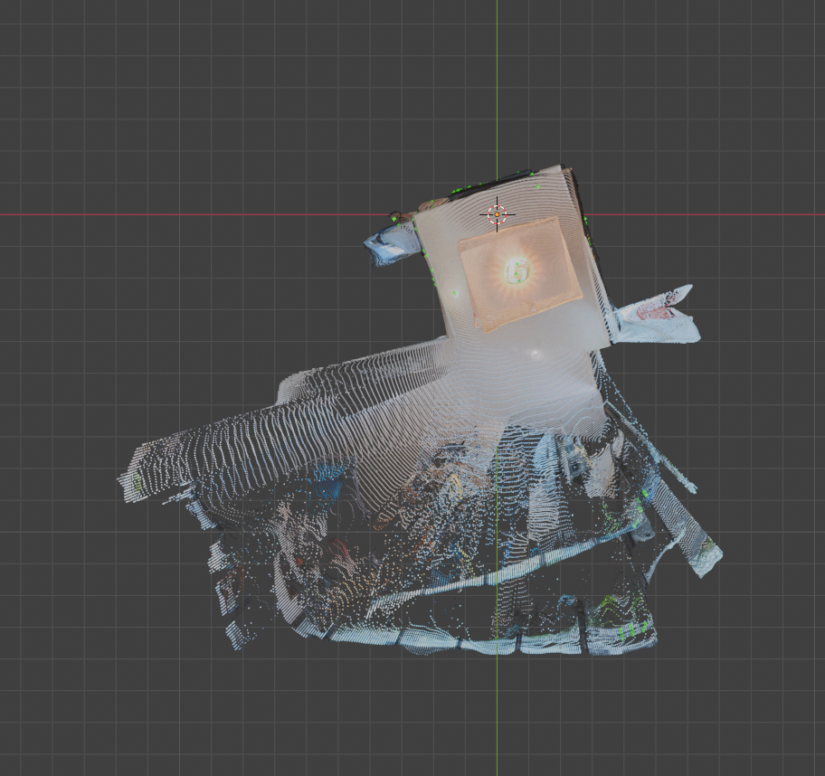
Another oddity shows if we look at the point clouds for the main entrance. The walls bow in considerably. From close up, these warped angles appear across the entire output of point clouds.
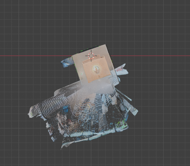
Testing Tool B
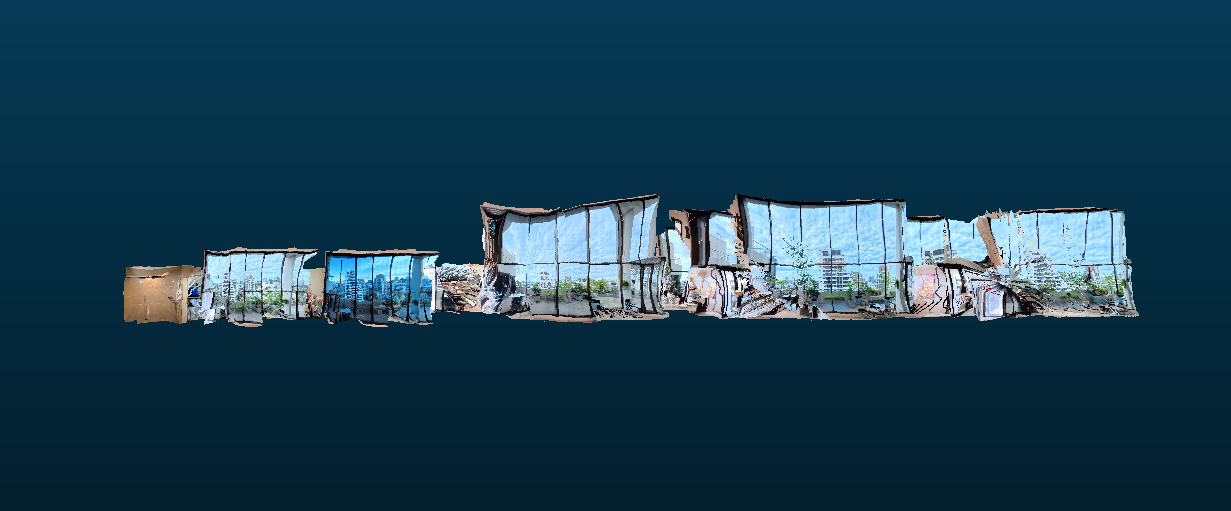
Running a similar series of rectangular images through Tool B we received a series of results with qualities considerably different than Tool A.
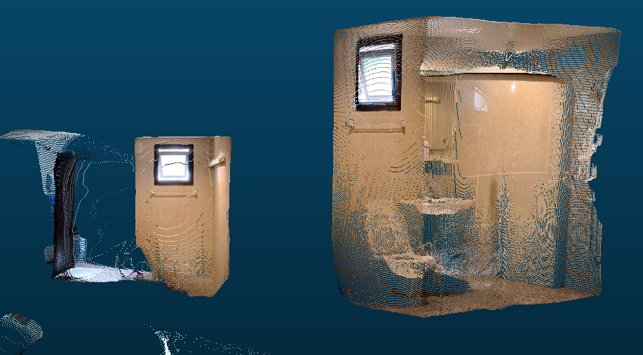
The scale across images at times appeared consistent; However, they often were not. Look at the storage closet washroom in this example. The size of one is almost half the size of the other!
On the bright side, we can see across images that there is far less warping and walls appear straight.
Verdict
The goal of the depth estimation step is to prepare an estimate of what the geometry around the camera should look like in 3D. The metric accuracy of Tool A would support a result where near-accurate measurements could be made against the 3D geometry. To get this benefit we would have to overcome two problems. We would need to resolve the warping AND ensure scale consistency even across outlier positions like the staircase. For Tool B we cannot rely on metric accuracy. We can rely on geometric consistency and would only need to solve the scale problem in order to use them.
I decided to proceed with Tool B as it is able to satisfy the requirements of the step with the least added steps required. Metric accuracy would be a great feature, and can be added in the future as tool B’s output should give us a 1:x scale replica in most cases.
Convert Matches to 3D
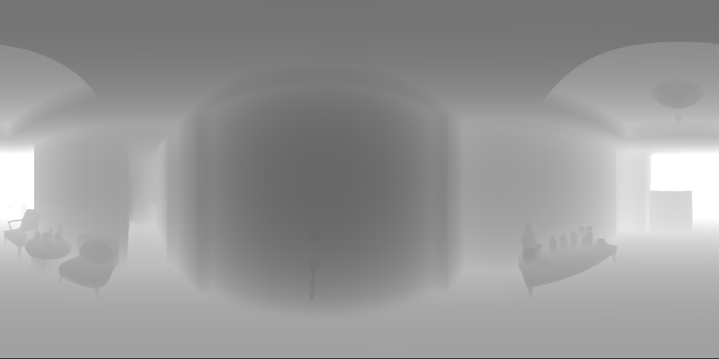
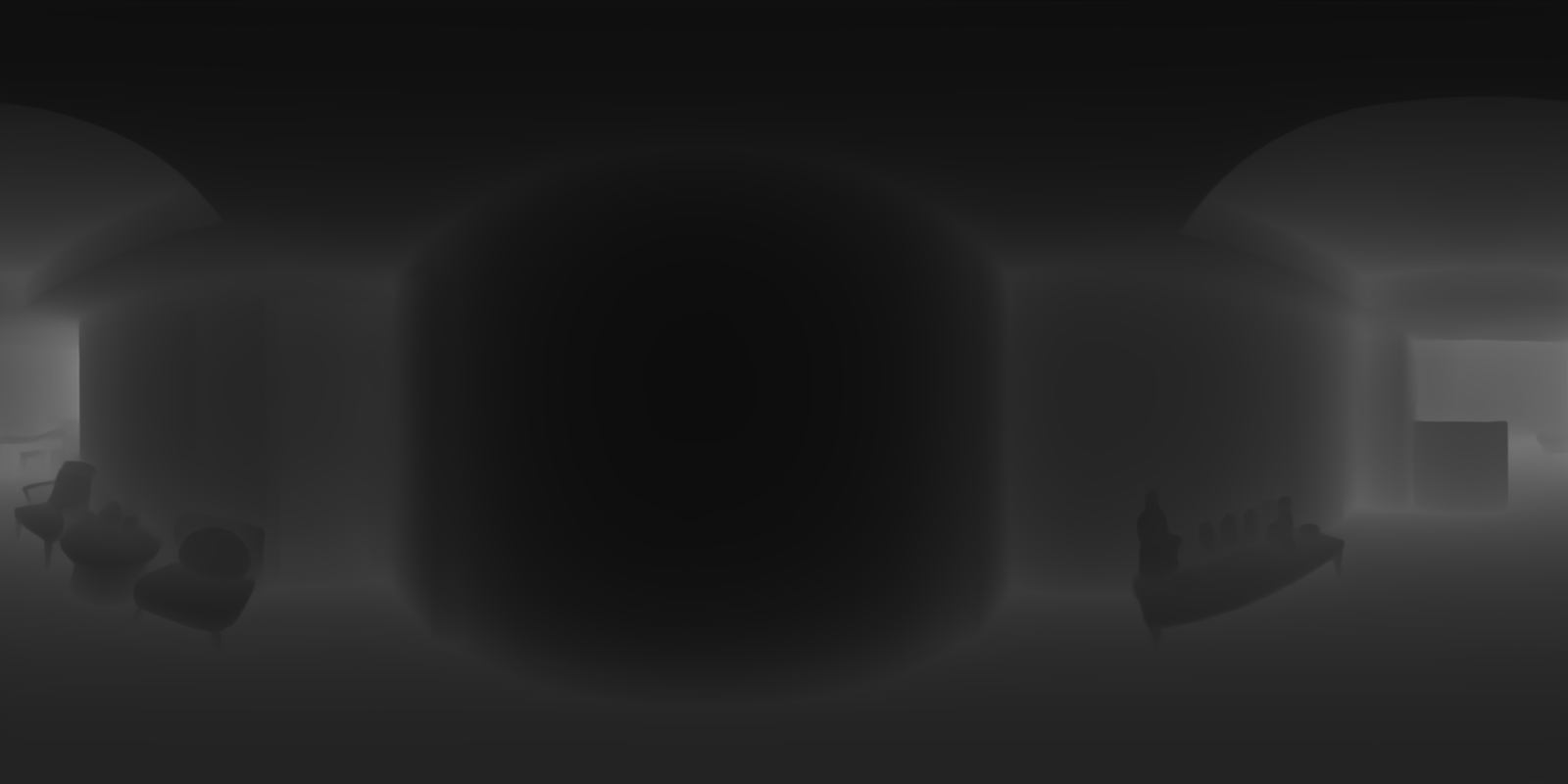
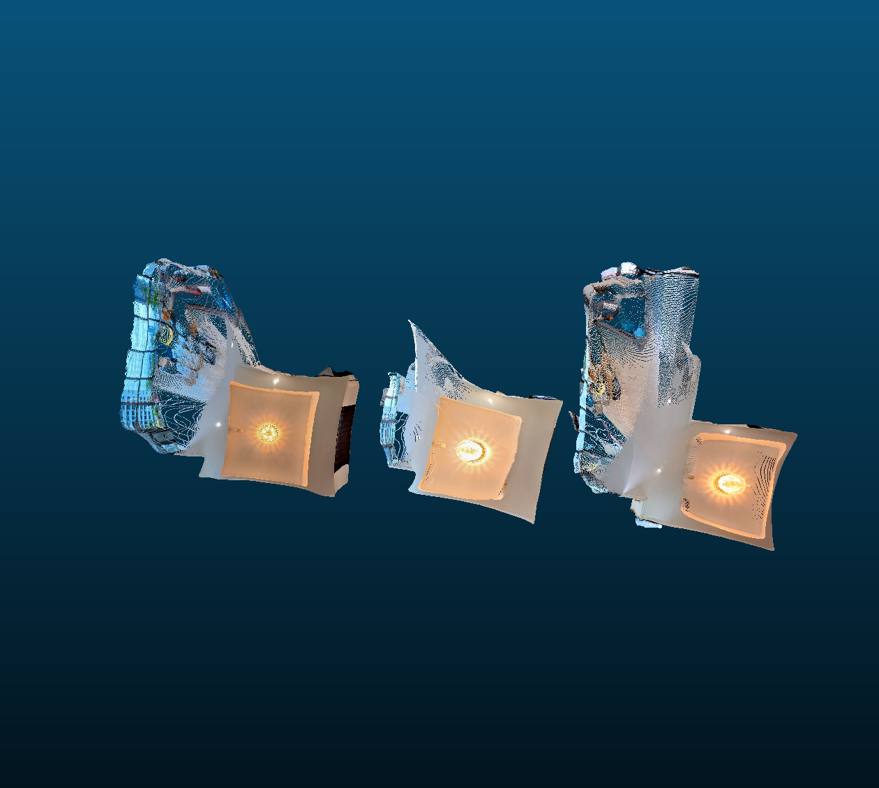
The matching points output by an earlier step represent where points match on a 2 dimensional image (x, y). We can determine which points match in the 3D point clouds by converting these matchers to the third dimension (x, y, z). Increasing a dimension is an additive process, and we can use the depthmap data output by the previous step to do so. The cloudy gray exr file is a 2D representation of depth where the color gray represents the distance from the camera. This information is paired with the 2D matched output to generate the matching points in 3D.
Align Point Clouds
Goal
Currently we have two 3D representations of our scenes, called point clouds, and 2 sets of matching points in 3D. With this information, we can put the matching points into a tool that determines the change to scale, rotation, and translation (delta S.R.T.) that aligns the points. Again, I chose two tools to compare and see which gave the best results.
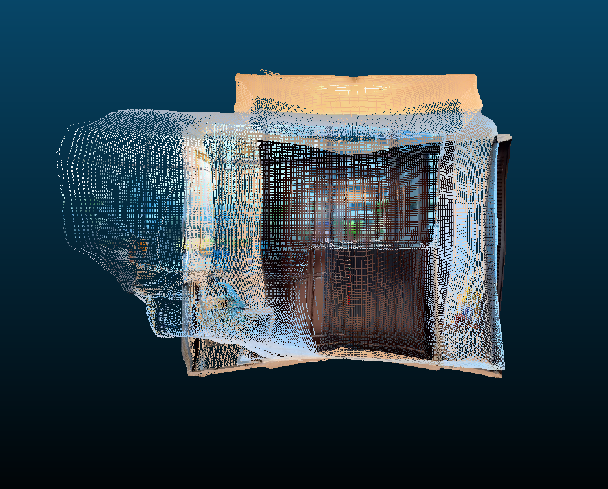
Tool A
Tool A was able to match most of the points and offer an incredibly improvement from the unmatched original. From the top the point clouds seemed perfectly aligned. From the side told a different story. While the points were aligned the scale of the point clouds was not being properly considered. The outlined inner point cloud was squished and much shorter than the other point cloud, thus the floors and ceilings did not align. This is due to tool A relying on ALL matching points, including the false ones we noticed earlier.
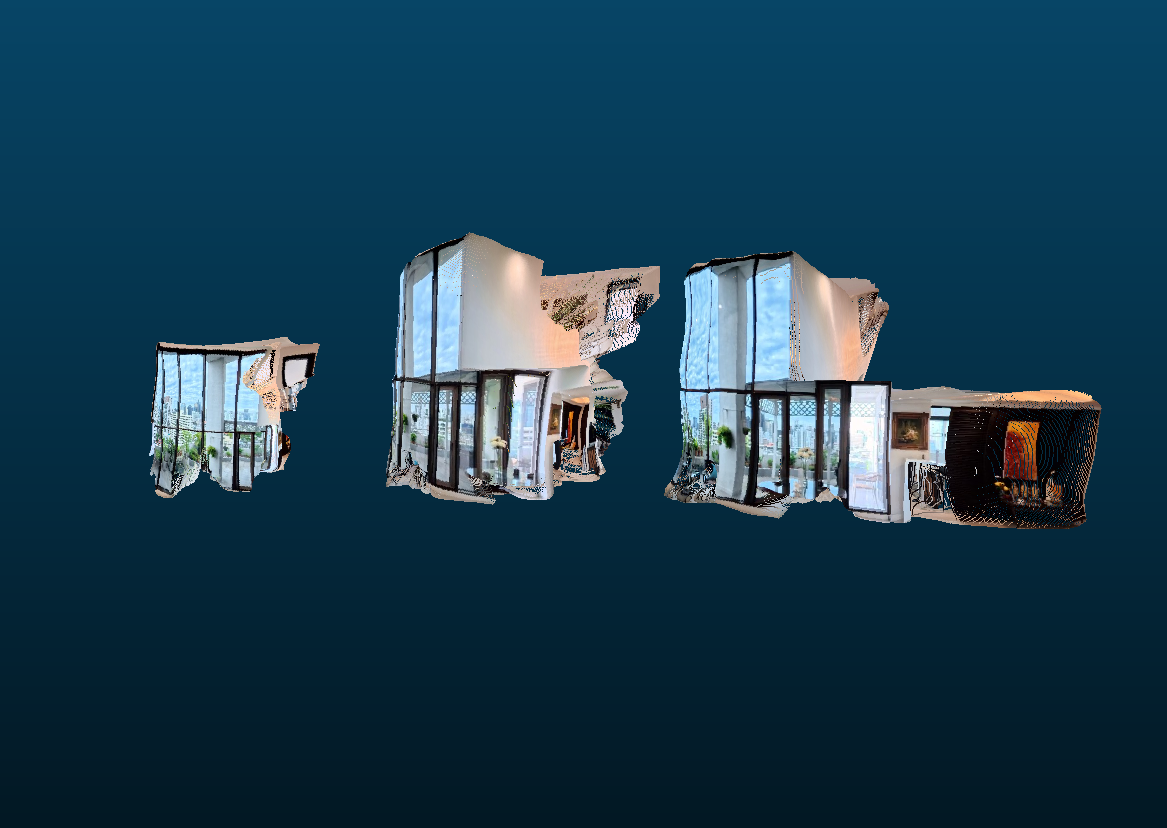
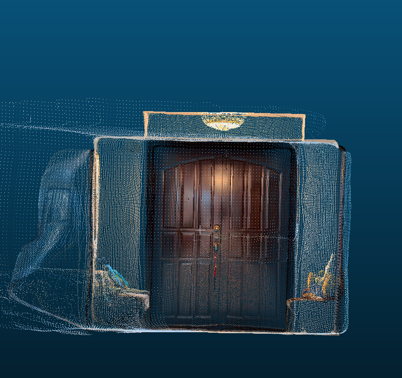
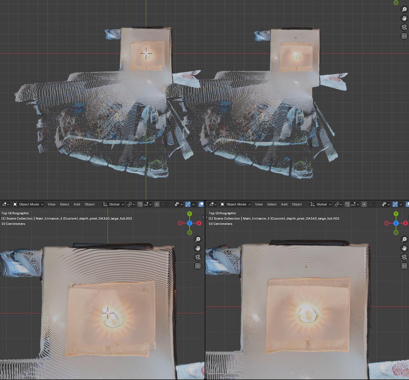
Tool B
Tool B’s output again came very close to the solution but slightly missed the mark. From the side view we can see that the scale is now correct and aligned. From the top view the scale continues to be correct; However, we notice a new problem. The rotation is slightly off. The top right corner of the room can be seen sticking out. Tool B’s approach ignores the lest likely matches. This removed the bad influence of the false positives affecting vertical scale, while also removing the good influence of some matches that contributed to alignment.
Verdict
Both Tool A and Tool B output misaligned point clouds. Both the problem of scale and rotation are likely solvable now that each point cloud is much closer to their accurate positions. Therefore, a refinement step will be necessary after the tool’s output. I decided to proceed with Tool B, as the alignment overall is much closer and is likely to be easier to refine.
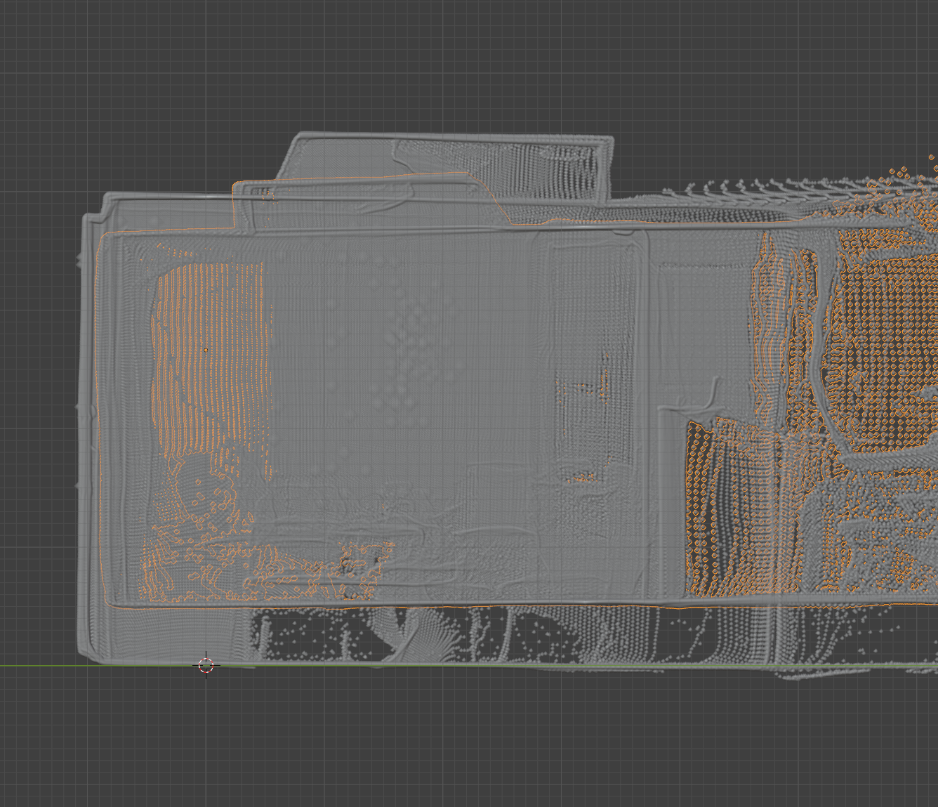
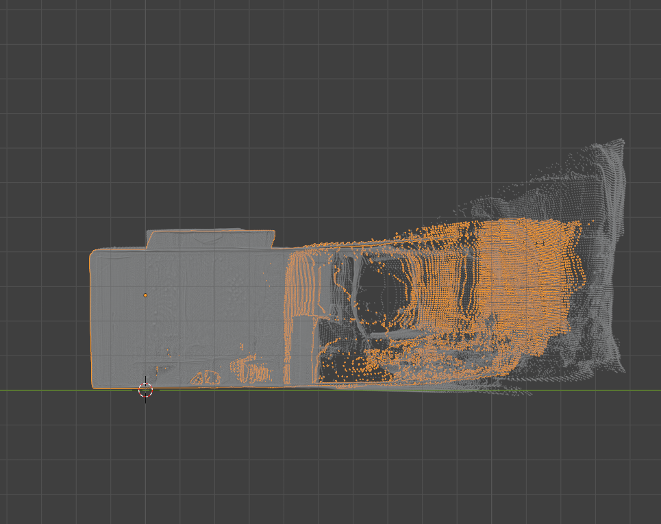
Refinement
Tool A and B are called global refinement tools, which rely on the matched features to align the two point clouds together. Now that the point clouds are incredibly close, a new Tool C can come in. Tool C offers local refinement, it does not consider the matchers and instead looks at all of the local points to determine the delta S.R.T.
After running Tool C on the result from Tool B, the output was incredibly closely aligned. The before and after can be seen pictured above. After closer inspection I did notice that the distance between the walls was very slightly off. Perhaps the relative distance between the walls output in the depthmap step was incredibly close with a minor imperfection. Perhaps this can be resolved in a future implementation where nearby points are merged based on color or other criteria.
Camera Position
An added benefit of aligning the point clouds is that we get the camera’s relative positions. Each point cloud originates with the camera at position 0,0,0. When each of the alignment steps are performed, we get a delta S.R.T. This change in scale, rotation, and translation can be applied to the 0,0,0 position, and represent the alignment of our camera to the camera at the origin of the other point cloud.
Convert Point Cloud to Mesh
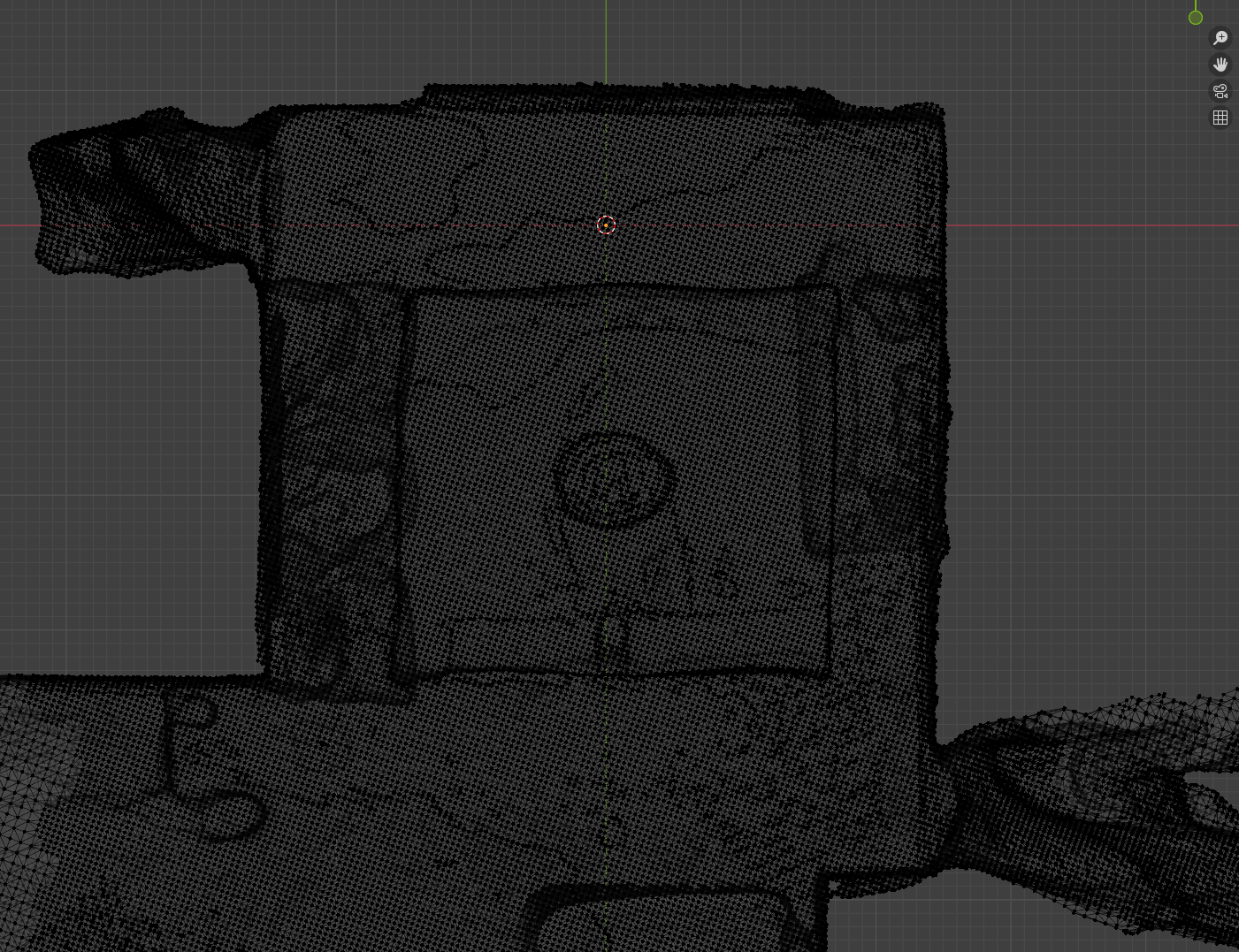
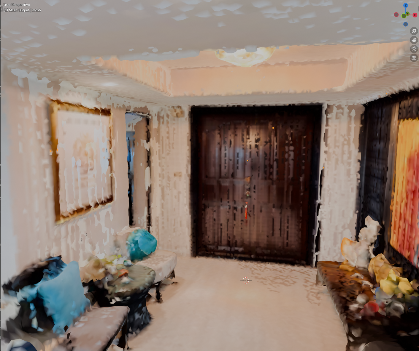
The final step is to take the aligned point clouds and convert them into a 3D mesh. Many tools exist to perform this process. To complete this proof of concept I picked a common tool and assessed the output.
For the first iteration, completed in under a week, I am incredibly satisfied with the output. The geometry is accurate overall, there are no gaping holed in the main room, and it is visually apparent where you are and what the objects should be.
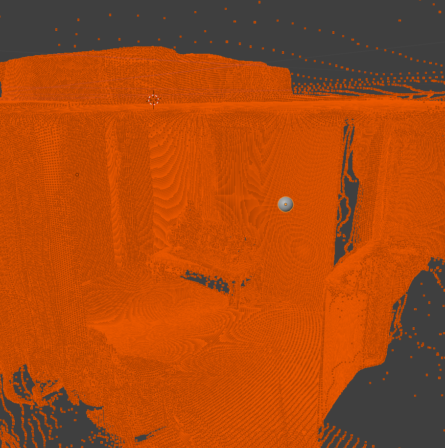
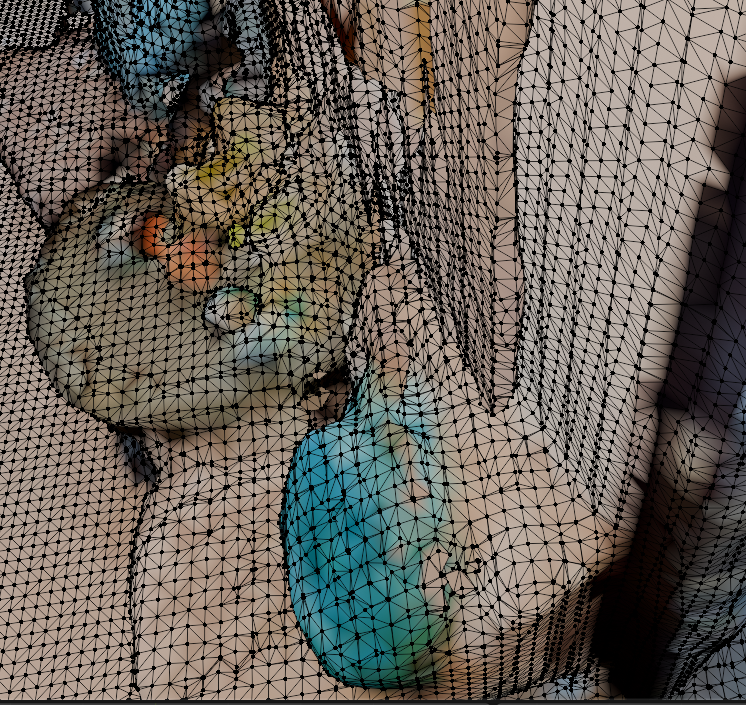
While successful, there is still much room for improvement. The texture is currently based off the individual points used in the point cloud. This is very low resolution and leaves a blotchy look across the surfaces. The color across the same wall also slightly varies from image to image further enhancing the blotchy look.
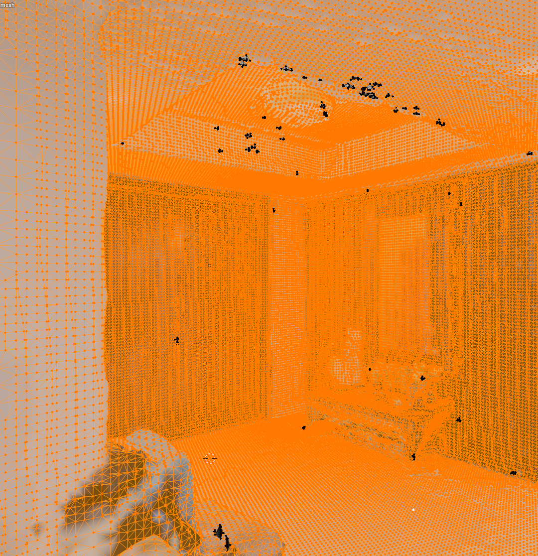
A closer look at the geometry reveals further challenges. The topology is incredibly dense. This leads to more computation and larger file sizes. There also appears to be many small floating bits of geometry. This is likely from floating areas in the point cloud that didn’t align close enough with their nearest neighbors. And I noticed one side of the room had 2 layers to its wall. This is likely from the parallel points we noticed earlier during the alignment phase.
Summary
This week I proved that sparse 360 imagery alone can be sufficient to reconstruct a 3D mesh. Throughout this process different tools were considered, tested, and decided upon. Each tool often came with outputs imperfect for the task. In each case, I was able to find and implement a step to refine the output and inch closer to the final result.
Throughout this exercise many concepts have emerged around opportunities to improve various steps in this pipeline. I hope to iterate upon this in order to better refine the process and narrow in on a more complete and visually pleasing result.