
Accomplishments
- Built Docker Images
- Refactored Proof of Concept
Bonus
- Depth Model Comparison
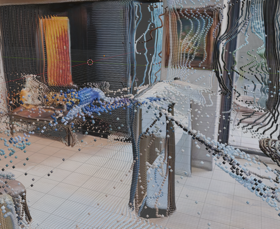
- Many Image Point Clouds
This week’s goal was to take a rapidly built prototype and convert it into a foundation that’s simpler to deploy and adjust. I set up the files to work with a tool that packages them in a way that they can easily be run on any device. I also rewrote much of the code so that steps can happen independent of each other. As a bonus, I was able to begin modifying the components to accept more than 2 images for 3D reconstruction, and generate a combined point cloud.
Built Docker Images
The goal of Docker is compatibility. It packages a program along with all the tools it needs to run on any system. It’s kind of like having a universal adapter where, no matter where you go you can plug into the wall and charge. A docker image is the output. This includes the program and all the tools needed to run it anywhere.
Creating the docker image comes with some steps and considerations. This includes writing out which tools the program will need to run. Since our 360 to 3D pipeline includes multiple smaller programs, it is common for their needs to overlap. To satisfy this we use something called a “base image” which includes all of the shared tools which may be required. Setting up the base image can be tedious, as it takes time to determine the best version numbers of each tool which are compatible with all the rest. For small tools quantified by Kilobytes or Megabytes, this may not be concerning. However, multiple programs in this pipeline rely on tools that are Gigabytes in size! Reusing these is very important to preserve efficiency and save on system memory.
Another consideration is shared storage. Docker images by default write within their own spaces and do not have access to each other. This lead me to creating a “shared volume”. With a shared volume, each image can contribute, read, and write their own data to a shared space. This is helpful in large data scenarios (like 360 photography) where each program may require access to the full dataset.
Preparing the Docker images helps transition a rapidly produced proof of concept into something less brittle, that can be preserved and recreated on any system running Docker.
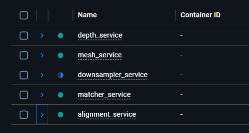
Refactored Proof of Concept
A rapidly made proof of concept (POC) often includes shortcuts to more efficiently determine the effectiveness of a process. Upon approval, a new design should be constructed which includes the slower developed supportive steps which improve the ability to efficiently make changes and preserve functionality going forward. I converted my POC from sequential “get the job done” steps into a more modular “accomplish this step” approach.
I added application program interface (API) endpoints to the program. Instead of manually updating a file and running the program once, I can now call the program any time and submit different information at that time. This gives swift flexibility to where, when, and how I interact with it. This also gives me a better opportunity to multi-task. I set up each endpoint to begin a job. Instead of waiting for the sequential job to be completed, I can now periodically request a status update from a different API endpoint. The benefits of this will be much appreciated as processing time increases in line with the size of the data set being uploaded.
Breaking down sequential processes into atomic steps decouples logic and improves cohesion. This ensures that each atomic step only relies on what it absolutely needs and only affects what’s crucial. Setting a foundation in this manner permits future steps to be added with narrow impact to the other programs.
Bonus: Depth Model Comparison
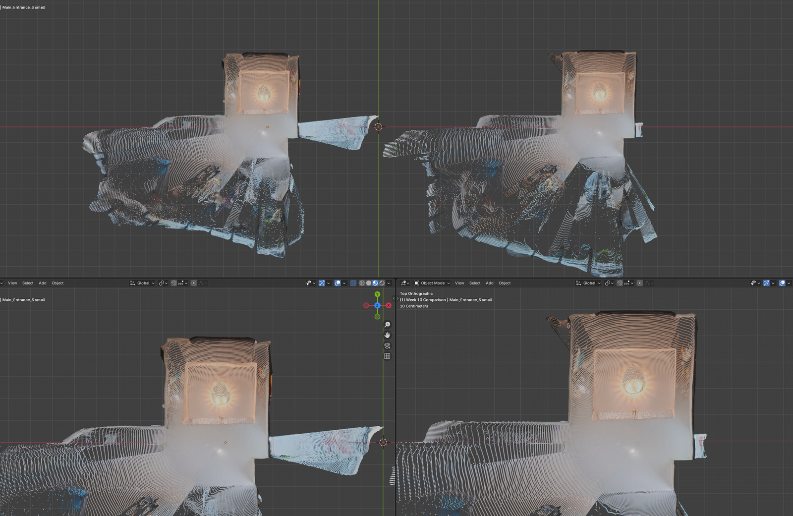
This week I experimented with the different machine learning models in the tool which calculates the depth for each photo. One model seemed to offer improved depth detection through doorways. This will be helpful when feature matching must take place beyond a shared doorframe.
Overall the newly tested model appears to offer similar results. A few small oddities have been identified, like a strange bubble appearing around the entryway table, and a broad stretching happening to a small plastic standee placed a shelf.
I believe a step to clean up, reduce, and combine point clouds will be needed. While these appear to be new issues, I believe they may be solved by a clean up phase and the benefits of expanded doorway depth may be retained.
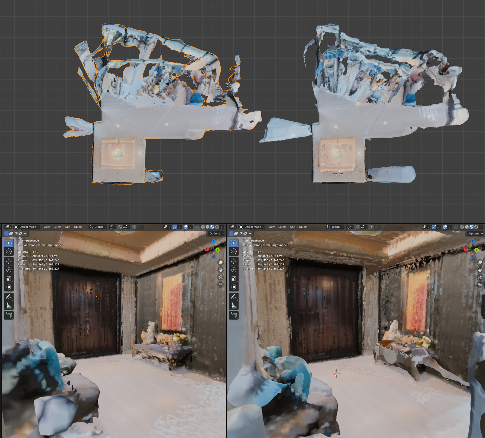
Bonus: Depth Model Comparison
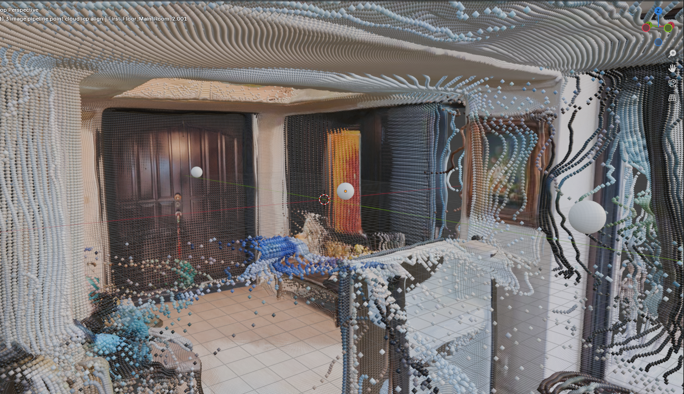
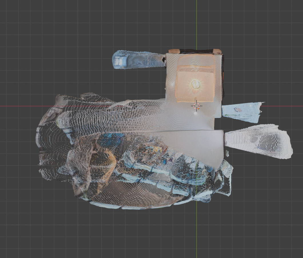
With the improved foundation afforded by the containerization (Docker) and refactoring I was able to more swiftly modify the process to remove the previous limit of 2 images for pairing. A myriad of minor tweaks and process changes were necessary for this step. The new layout made it quick to identify and apply the required changes. The point cloud result excites me. This visualization represents the processes ability to not only combine two 3D projections, but also refine and expand that combination as more are added.
Making these changes also called to mind the many changes that are necessary to perform this process efficiently as the number of photos scales. Steps like downsampling and generating depth maps scale 1:1 with the number of photos uploaded. If it takes a photo 0.1 seconds (s) to generate a depthmap, each extra photo will be an extra 0.1s.
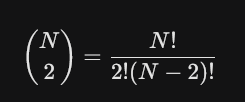
This scaling is not so true for our feature matching step. Combining two photos, A and B, takes 1 step, matching A-to-B. Combining three photos takes 3 steps, matching A-to-B, A-to-C, and C-to-B. This can be written as a formula, and simplified to N * (N – 1)/2. That is the total number of matches for the N number of items. This grows incredibly fast. While 4 items only need 2 more matching steps (6 total), 100 images would require 4,950 matching steps. 1000 photos would require half a million!
For 100 photos, most of the images shouldn’t even be attempted to match together. Consider a 3rd floor bathroom and a 1st floor kitchen. These two rooms (hopefully!) have no overlap. While this may be trivial for a human to see, it’s much more challenging for a computer to determine this. As we saw in Week 12, similar, but different, structures in an environment can contribute to incorrect matching.
The results discovered while reconstructing over two photos illustrate how negligible faults in a process that match two photos rapidly grow into tangible impurities as the data scales. While most data sets should still calculate matches efficiently on modern hardware, it’s important to be aware of the ceiling of input data and the concern for the greater influence false positives may have on the final reconstruction.
Summary
This week I created a modular sequence of containerized steps capable of accepting two or more equirectangular images and producing a combined point cloud and 3D mesh. This effort makes the programs portable, and capable of running on any machine which includes Docker. The programs were also developed to be modular, reducing coupling and improving cohesion. Now fixes and improvements should be more efficient to apply both cognitively and manually. And expanding the reach of the workflow from 2 to multiple image inputs demonstrated its ability to refine and improve a reconstruction while also illuminating new opportunities for increased efficiency.