
Accomplishments
- Defined Requirements
- Drafted Reconstruction Plan
- Reconstruction – Second Iteration
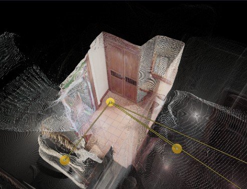
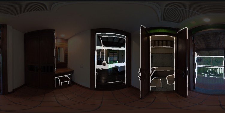
At this point we have taken 360 images and accurately graphed them and estimated the 3D structure as point clouds, or a matrix of floating points in 3D. Each camera has its own point cloud, and these point clouds overlap. To take these floating clouds of points and make a solid room we must identify these overlaps, and other irregularities, in order to make the structure as realistic as possible. I reviewed the current state of the point clouds and the issues that came up and began reviewing tools and techniques. Through this I drafted a plan to attempt to use these tools to solve the problems currently faced and began to implement it.
Defined Requirements
Every problem comes with a goal. The better the goal is defined, the more likely we are to achieve it. The goal for the reconstruction step starts off simple: “Convert overlapping 3D point clouds into single 3D mesh”. In practice, it grows much more complicated than that.
You might recall that I had previously designed a reconstruction phase in week 17. These fused point clouds looked great from many directions, but not all. A variety of issues had appeared. One phase used cube-mapping which ripped seams through entire rooms. Another stage attempted to vote on geometric confidence, and at times would delete information on the other sides of a wall or retain hallucinated geometry in the wrong spaces. I took note of these and other issues and began fresh in assessing what a viable reconstruction pipeline would look like and need to perform.
I also took the time to identify concrete examples of issues already found in the point clouds. Naming these issues and identifying their locations will give us valuable tests we can perform to ensure the pipeline is performing to our expectations. The issues to be tested include the following:
Hallucinated Depths: The current depth estimation approach struggles within doorways, and the information stretched into the other room is often false.
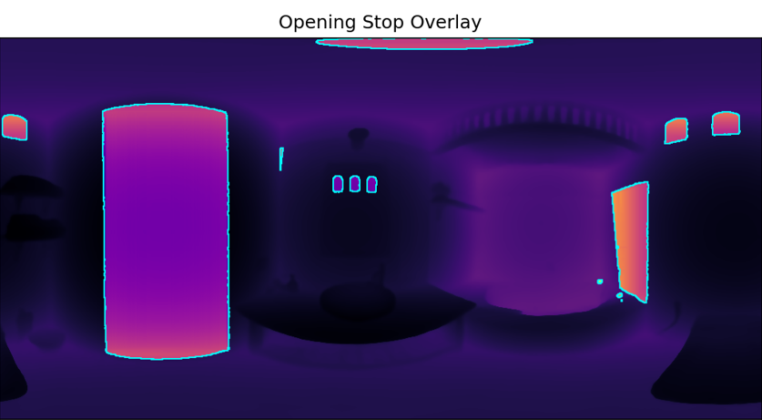
Flat Doorways: Some doorways have no depth at all and appear flat along the wall. A virtual tour needs to see through these gaps in order to display hotspots. These flat surfaces must be opened.
Sharp Edges With No Alternative: Cameras can only see information from their perspective. So flat walls or sides of cabinets not visible to the camera do not initially receive depth data and appear as holes in the geometry. If no other camera sees that surface we must make a best guess at what that surface could look like so that we don’t have surprise holes everywhere.
Sharp Edges With Alternative: If one camera sees a sharp edge, and is unsure what’s behind it, another camera might see what is actually behind the edge. In cases like this, the camera that can see the geometry should be able to merge it with the other camera.
Misplaced Surfaces – Far Apart: Depth accuracy is only consistent until about 2.5m with the current tool. After that, depths may band or stretch. In a large room this can cause depths to appear in the wrong place or beyond a wall. We must identify where those walls are and either merge or remove the wrongly positioned data.
Misplaced Surfaces – Close Together: Even nearby cameras can estimate depths at slightly different positions. The same wall may appear at different positions all within a foot of each other. This geometry should be identified as representing the same thing and merged into one single wall.
These tests, among other things, represent the challenges faced in converting estimated depth maps into accurate 3D objects.
Drafted Reconstruction Plan:
With the requirements outlined, along with given information attained through previous phases in the process, we can begin drafting our plan. This week’s process consisted of over 10 steps. I will summarize the concepts here.
The majority of time doorways provide inaccurate information. They are the most important part of an image for positioning, however the depth is incredibly misplaced. I determined that removing it altogether made the most sense. This meant that no geometry through doorways would appear or interfere with better geometry on the other side.
It was also important to ensure that cameras do not provide empty votes to geometry on the other side of doorways. When voting a line is drawn from the camera to the cubic (foot, meter, centimeter, etc) that is being voted on. Usually this stops at the camera’s own geometry, however, if we remove the geometry through a doorway it could go infinitely! To avoid that I added a step to create an invisible wall right in the opening of a mesh that blocks the line, or ray, when it reaches it. This ensures negative voting remains within the bounds of the known good geometry at all times.
Edges, as previously mentioned, often result in empty space or missing geometry. I added a step that stretches out a flat surface between all edges, like a curtain over a window. These points weakly cover the flat space. They will remain if nothing else determines them to be inaccurate.
Identifying occluding walls was another important step identified. When a far camera tries to draw its wall on the other side of a much closer camera’s wall, that closer camera should block the ray, or line, from going through it. This also applies to empty space voting, so that the far camera cannot remove geometry it should not be able to see in the first place.
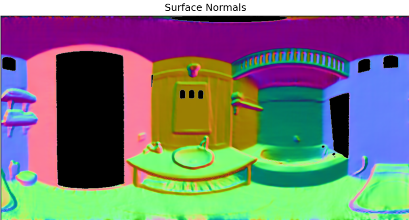
Getting surface normals remains an important step. This labels a direction that the point is facing. Ceilings face downward, floors face up, some things may face at an angle. This will help us identify two sides of a wall when they overlap, as ideally they should face away from eachother.
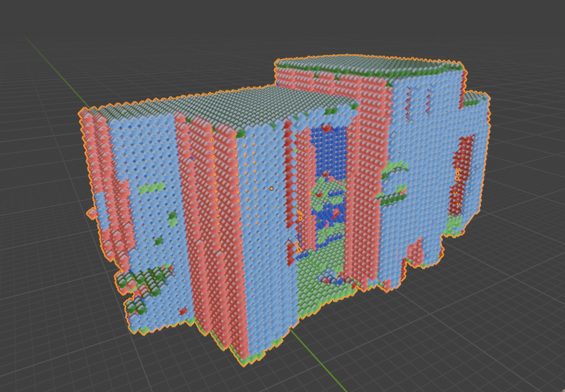
And then there was the question of how we would vote and apply the results to a completed mesh. TSDF is an acronym for a form of calculation that performs this voting. The results would then flow in to one of two functions, one using a system called Dual Contouring, and another using a system called marching cubes.

If successfully, this series of procedures has the potential to provide a solid and connected 3D object made out of overlapping and falsy 3D point clouds. That output could later be decimated, or reduced, for a smaller file size, and have textures, or image details, projected onto it for visual similarity to the real world environment.
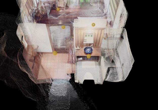
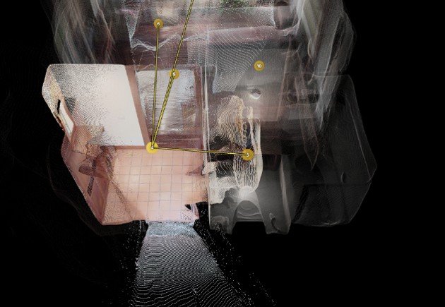
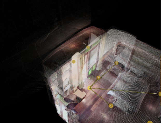
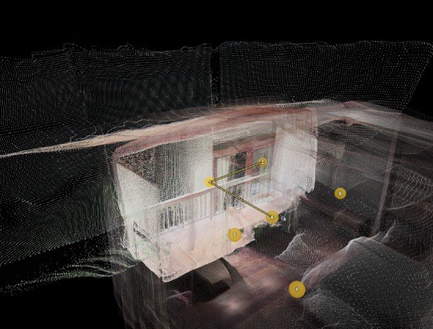
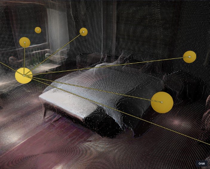
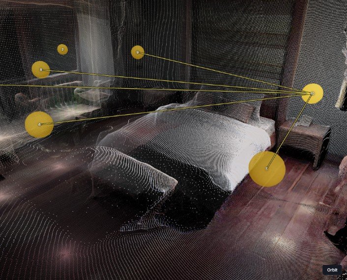
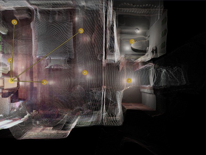
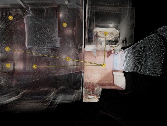
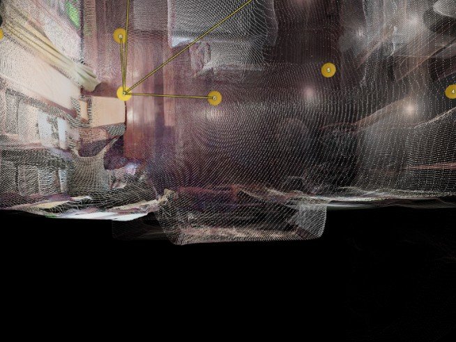
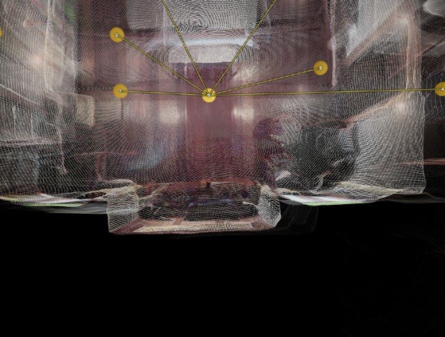
Reconstruction – Second Iteration:
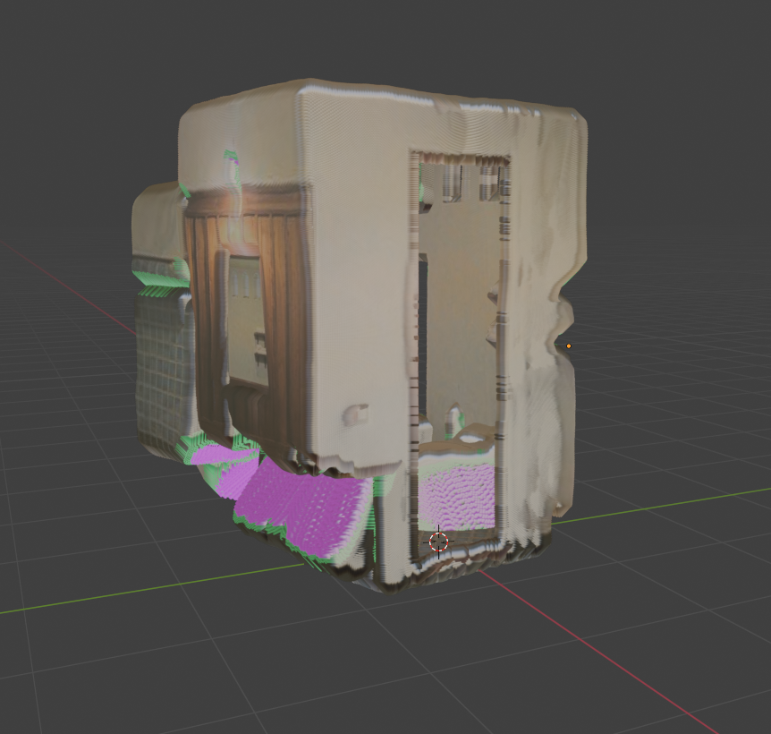
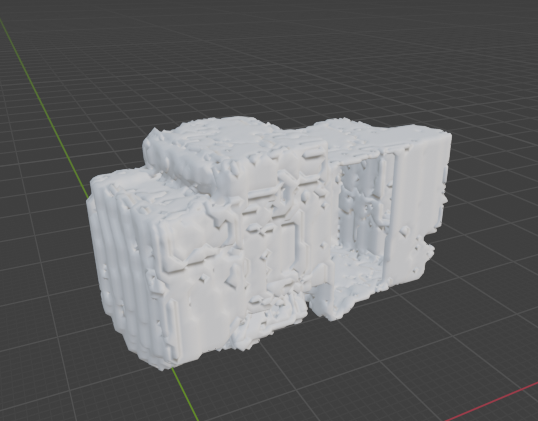
The images displayed in the previous section display results from various stages implemented this week. Doorway removal and stopping rays at doorway thresholds successfully solved a consistent problem from implementation 1, where holes were being cut behind walls. The same goes for identifying occluding surfaces.
Removing doorways and edges also drastically reduced misplaced geometry. Replacing the edges with “curtain” surfaces helped visually complete each individual room often only subtly different from the ground truth.
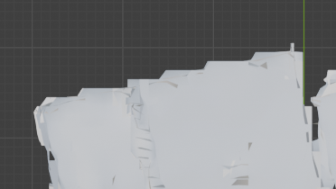
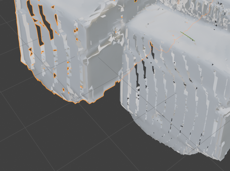
The challenges really began to display themselves when combining the points with their normals into structured meshes. The dual contouring workflow attempted resulted in visually identifiable spaces that were lined with ribbon shaped cuts and carvings. Initially this issue was due to each point only representing one normal direction, so when written each voxel, or cubic box to be meshed, was only allowed to face one way, removing the opportunity for angled walls and objects. This also contributed to aliased or jagged sides of the space, as well as loose and floating squares with inconsistent and overlapping connection points.
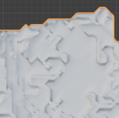
I also tried marching cubes. This too works voxel by voxel to reconstruct the mesh. It solved most of the issues noticed in the dual contouring attempt while generating new issues of its own. The geometry still appears stepped in some cases. In others there are strange impressions or embossed geometry that adds distracting artifacts to flat surfaces.
In review, this implementation appears to provide meaningful solutions to a few known problems. It successfully fills edge holes, and so far appears to properly control voting through doorway thresholds and known occluding walls. Adjustments will need to be made to identify the best solution to take this filtered point cloud data and construct a more accurate 3D model.
Summary
This week we transitioned, using our known camera positions and depths therefrom, we began designing and implementing processes to take this loose overlapping information and display an agreed upon structure. Challenges have been identified and resolutions have begun to be implemented. Progress is visible in areas like camera occlusion and edge hole removal.